
This set of parts is quite complex and the drawing in the accompanying build scheme is just showing it from one side, leaving a lot open for interpretation. And in this case, to be honest, the black and white isn’t of much help, having just the smallest amount of contrast.
So, I have asked Maxim for help and he sent me all the pictures he had of the Zil. thanks again, Maxim, they were helpful. However, the parts and the assembly still were quite tricky.
Here’s the end result, below it you’ll see the build-up. Perhaps these photos also can be of help for future builders of this vehicle.
Note: This was after I realised it would be easier getting all the wheels aligned if I would leave it off at first, adding the wheel later. Hence the paper rips at the wheel attachment points.

As interesting it was to ponder over those mechanisms (I really find that interesting to do), the reality was that I still had to puzzle with the parts a lot. In the end I think I got the right shape. It is a wonderful piece of technique in paper. Two swivelling parts that attach to the wheel complete the structure.
The only thing that now worried me was whether the wheels originally had to be able to rotate. If so, I am afraid mine won’t be able to do that. I made some sketches of how it would be possible and I presume that also would have been the case with Maxim’s wheel. The instructions however, weren’t that clear…
Anyway, I started to put the kit parts together and came up with this more or less exploded scheme for more clarity (really? I hope so...):
 |
| I really hope this can be of some help to future builders. The model is worth it! |
The numbering was off at some points, I marked that in the drawing above. The suspension arms of the mid wheels are different from the outer four, because the latter need to swivel. The number of parts point that out anyway but it isn't clear in the original instructions. Hey, with so much numbers, it's easy to make an error.
Anyway, here's how I began, the suspension base plate which will go at the chassis. Already added is the cap over the moving parts:


Next up was the bar at the bottom, which will carry the load of the wheels.

Below, the two small parts that attach to the wheel itself. They also will do the swivelling. Tiny parts with a big load.

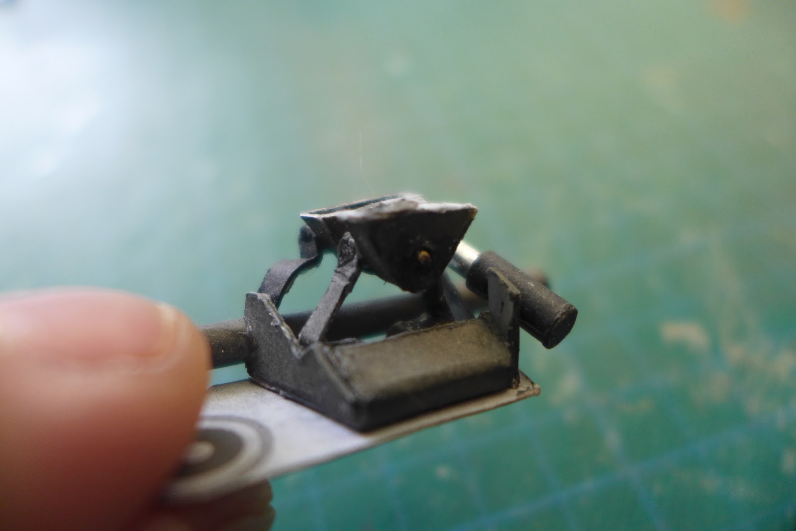
I decided to build the suspension up in two parts; the base plate and the swiveling parts added to the wheel. So this was what I ended up with on the wheel. First I added the pivots. The axle was a sewing pin. I used the head as a stop on top and cut off the bottom as close to the paper as possible. It was glued into place with a drop of CA on top and at the bottom. Note the arms of the suspension still are straight here. This is not good; they need to be folded into a shallow Z= shape to fit and to give the wheel the right camber. I photographed it in several angles to show the construction a bit more clearly:


The two small drums at the top part are added. These are glued to the suspension base plate. The lower arms attach to the big bar at the lower part of the suspension base.


Boom. A few stepa further. I forgot to take pictures. Here the shock absorber is added. There is a small part that goes at the top side of the cap part. The shock absorber attaches to that part. The bottom part is connected to the lower suspension arm.

Now note the somewhat messy folds in the lower suspension arms. I already glued them into place, the glue was dry and I couldn't rip them off easily. I decided to just bend them into shape here. The model will be static, and the rest of the wheels will look better.


Here's when I realised that to get a better alignment of the wheels, it would be better to first do all the suspension sets without the wheel. Then at the end, when all suspensions are attached to the vehicle, to glue the wheels. So I carefully ripped the wheel off of the suspension.


Now, looking at the photos of the wheel attached to the suspension, you will notice one important thing: this will keep the wheel from rotating. Maybe I didn't read the original instructions well enough. Maybe the wheel was supposed to consist of an inner and an outer hub, so it could rotate.
But this would also mean that the “hub” part of the wheel would be stationary while the tire part of the wheel would rotate, which is not correct. The video’s of the Zil clearly show the hub is also turning.
This would mean I would have to create an inner hub which would be attached to the suspension and which is held into place in the wheel by an enclosing ring at the back of the wheel - but leave the front hub attached to the wheel itself. Interesting thought and perhaps closer to reality as I think. I made some drawings of this to see if it would be possible in paper:

 |
| The curved arrow of course indicates the tire would rotate, not the stationary inner hub. Now look at the attachment of this construction. Two small triangles. Which also are able to pivot. Stress loads galore. |
To make these wheels rotate like this, I’ll have to do some significant demolition work and I am not even sure whether in the end the wheels and the suspension will handle the stress loads coming with the extra set of movements put upon these joints. Both parts only are connected by the two small triangular parts - with not a lot of surface (glue) area.
Taking into account that the outer two pairs of wheels also can swivel, this might cause the joints to easily rip apart if you would like to demonstrate the vehicle rolling and making a turn. Also, the wheel pairs aren't connected so they could end up pointing in different directions. And since this is going to be a model on display I’ll leave it like this. Even though the cranes and the steering section of the wheels are fully moveable.
Maybe when I feel the need to do the ‘salon’ version, I’ll try out this technique. Or even try to connect the front pair and the back pair with a system to synchronise the steering. Or maybe not. I'd rather build one in 1/100 or smaller for a diorama setup. (-;
Well, there you have it. A lorryload of interesting
I'll be having some time off next week so don't expect anything soon. But there will be new stuff coming up.
Thanks for stopping by and having a look.
--PK
No comments:
Post a Comment
attention spammers: all posts are moderated before placing.
you won't get through. you lose.